


Cemented Carbide T Model Sleeve
Product Description
A shaft sleeve is a mechanical component primarily designed to protect machine shafts and bearings, reduce wear, and extend equipment service life. Typically integrated into a bearing housing and positioned between the bearing and the shaft, it provides stable support and protection for the bearing.
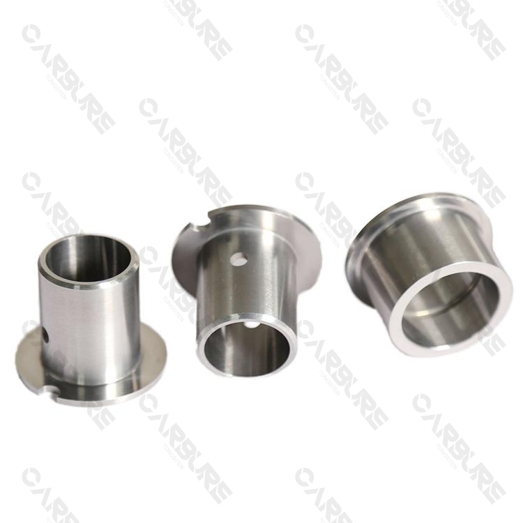
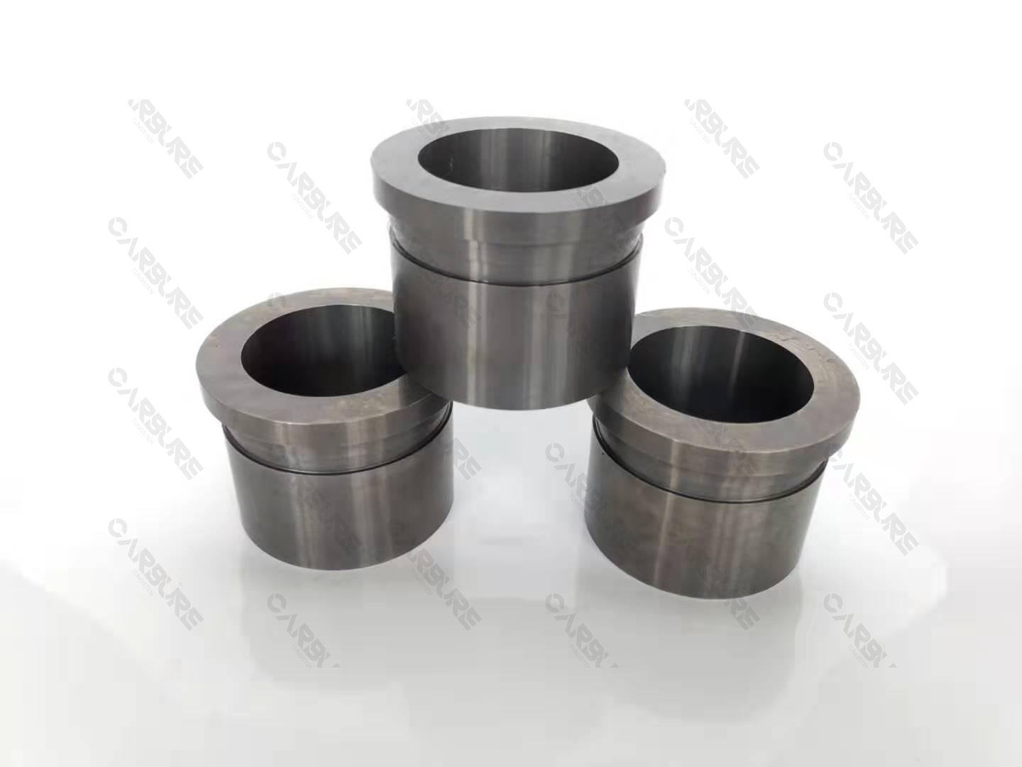
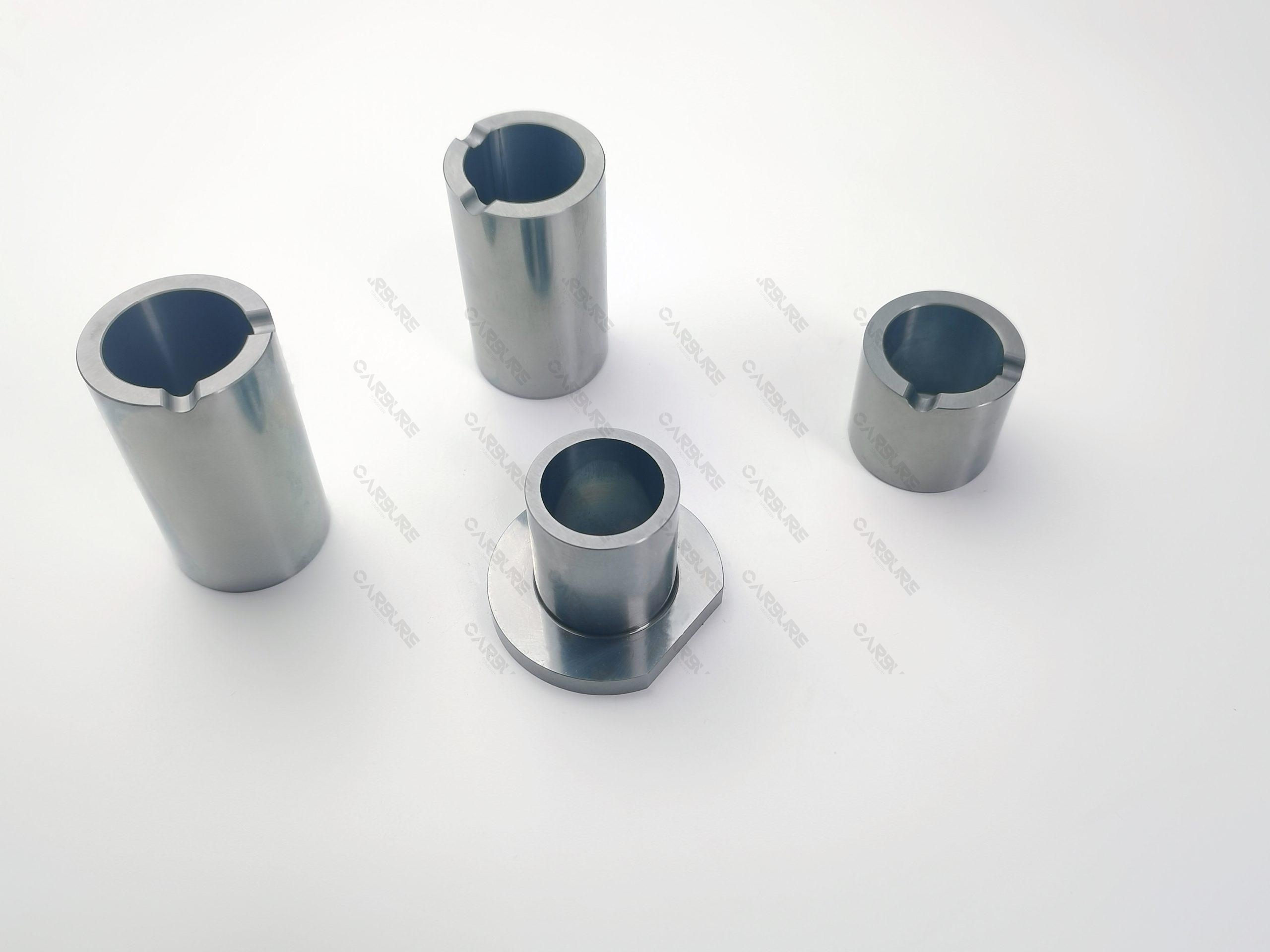
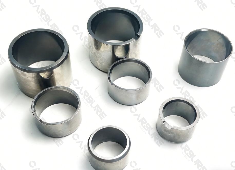
The tungsten carbide T‑sleeve is a specialized type of shaft sleeve manufactured from cemented carbide (tungsten carbide) featuring a “T”‑shaped cross‑section. This profile is engineered to deliver specific functional benefits, including precise positioning, reliable axial retention, and effective resistance to lateral loads. The design prevents unintended displacement in both axial and radial directions, ensures more stable support, and enables the reliable transmission or withstanding of forces in defined orientations.
Features of Cemented Carbide T Model Sleeve
Specification
1. Basic Material Parameters
| Core Material | Tungsten Carbide (WC) + Cobalt (Co), sintered via powder metallurgy (industry-standard base formulation). Other metallic binder phases can be added according to customized requirements. |
| Cobalt Content – Standard Grade | 3–8% |
| Cobalt Content – High-Toughness Grade | 10–25% |
| Cobalt Content – Custom Grade | Adjustable to suit specific operating conditions |
| Density | Approx. 14.5 – 15.1 g/cm³ |
| Density Tolerance | ≤ ±0.2 g/cm³ (Density decreases slightly with higher cobalt content) |
| Grain Size | 1.0 – 4.0 µm |
| Ultra-Fine Grain Size (Optional) | ≤ 0.8 µm available upon request for enhanced hardness and wear resistance |
2. Mechanical Performance Parameters
| Hardness – Standard Grade (YG8) | HRA 88.5–91.5 |
| Hardness – High-Hardness Grade (YG3X) | HRA 92.5–94.0 |
| Wear Resistance | Demonstrates 20–30 times the relative wear resistance of GCr15 bearing steel under the ASTM G65 abrasion test standard |
3. Tungsten Carbide T‑Sleeve Dimensional Parameters
| DIMENSIONS OF T-SLEEVES (mm) | ||||
| D | d | C | F | H |
| 13.0-59.0 | 3.0-51.0 | 8.0-56.0 | 22.5 | 25.5 |
| 35.0-51.0 | 22.0-37.0 | 28.0-41.0 | 11.0-13.0 | 15.0-25.0 |
| Noted: a=1.6,3.2 | ||||

Typical Application
Machinery Industry: In machine tool spindles, high‑precision engine crankshaft supports, and heavy‑duty gearboxes, tungsten carbide T‑sleeves support high‑speed or heavily loaded rotating shafts. With a typical radial load capacity exceeding 200 MPa and an axial load capacity up to 120 MPa, their performance is unmatched. Featuring a hardness of HRA 81–94 and a bend strength 2000-3000 N/mm², their wear rate is only 1/8–1/10 that of traditional bronze bushings. They can maintain spindle radial runout ≤5 µm and extend major equipment overhaul intervals from 6–12 months to 3–5 years, significantly enhancing operational precision and stability.
Automotive Industry: Used in critical friction pairs such as engine crankshaft main journals, camshaft supports, and transmission shafts, these sleeves reduce the coefficient of friction to 0.10–0.15, improving mechanical efficiency by approximately 1.5–2.5%. Their low thermal expansion coefficient (5.0–6.5×10⁻⁶/°C) ensures stable clearances across a –40°C to +250°C range. In transmissions and steering systems, they withstand over 10⁷ load cycles with wear under 0.02 mm, aligning component lifespan with vehicle service life and drastically reducing failure rates.
Metallurgical Industry: In continuous caster segments and rolling mill work roll chocks, these sleeves operate continuously under temperatures of 600–800°C and specific pressures of 150–250 MPa. They retain a hardness ≥HRA 80 at 700°C. Subjected to scale, cooling water, and impact, their service life is 6–10 times that of high‑chromium cast iron or welded overlays (typically >12 months), reducing unplanned downtime by 40–60 hours per replacement and improving product dimensional yield by 2–5%.
Petroleum & Chemical Industry: In oilfield injection pumps, chemical process pumps, and centrifugal compressors handling sand, H₂S, and Cl⁻, these sleeves exhibit a corrosion rate ≤0.05 mm/year per ASTM G31. Under pressures ≥25 MPa and speeds ≥8,000 rpm, their radial wear rate is <0.005 mm/1,000 hours. This ensures mechanical seal integrity and extends continuous run times for pumps/compressors from 3–6 months to 18–24 months, significantly mitigating unplanned shutdown risks.
FAQs


Get Your Customized Solution
Our team and engineers are ready to provide the most cost-efficient solution for you.